after it was subjected to the improvement: Standard
Penetration Test (SPT) and Cone Penetration Test (CPT).
The tests analyzed:
· Liquefaction
· Bearing capacity for the most critical footings
· Settlement analysis for the critical footings
considering the interaction effect of adjacent foundations.
All calculations were in accordance with the
international BS/ASTM standards.
release the pounders, delivering, in a single blow, the energy
equivalent of 1,200 ton/m. The massive impact of the falling
weight triggers a series of actions:
· Immediate densification of granular soils
· Generation of a compression wave that builds pore water
· Generation of high energy shear and surface waves that result in
· Speeding up of the consolidation process.
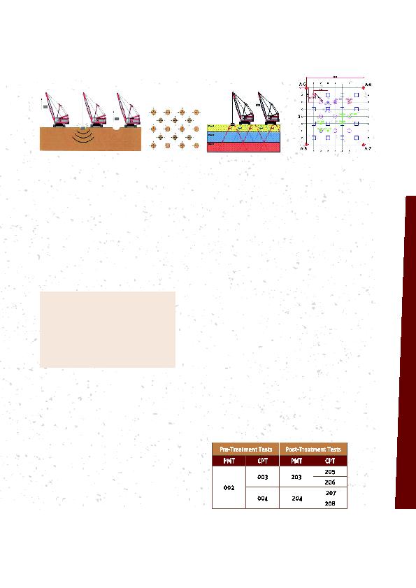
contractor created an onsite calibration area (Figure 3).
The quality control tools selected were the PreTreatment
and PostTreatment Cone Penetration Tests (CPT) and the
Pressuremeter Tests (PMT).
The tests evaluate subsurface conditions from the relative density
point of view, before and after the improvement process. Also,
two Heave and Penetration tests were carried out to determine
the ideal number of blows.
· Number of blows per print
· Drop height
· Type and weight of the pounder
· Number of phases and passes.
turned to a second solution, Dynamic Compaction.
It targets unsaturated and saturated granular
materials, dramatically increases the geotechnical
properties of soil, and has the advantage of
reaching great depths.
with 3035% fines content. It is well adapted
to large areas and results in uniform ground
conditions all over the site. The process of Dynamic
Compaction is illustrated below Figure 2.
for each impact position and in several phases,
following a preset (usually a square grid)
from the surface to intended depth of treatment
tests showed it to be unsuitable for the prevailing
subsurface conditions. This technique was only
able to treat layers up to maximum 2 m in depth.