(Parcel 2.11) being recalculated according to LEEDrecommended
species, density and microclimate factors. When the landscape
factor KL method is applied, total water use is reduced by 57%.
Furthermore, no potable water is used.
number of efficient irrigation technologies and design practices.
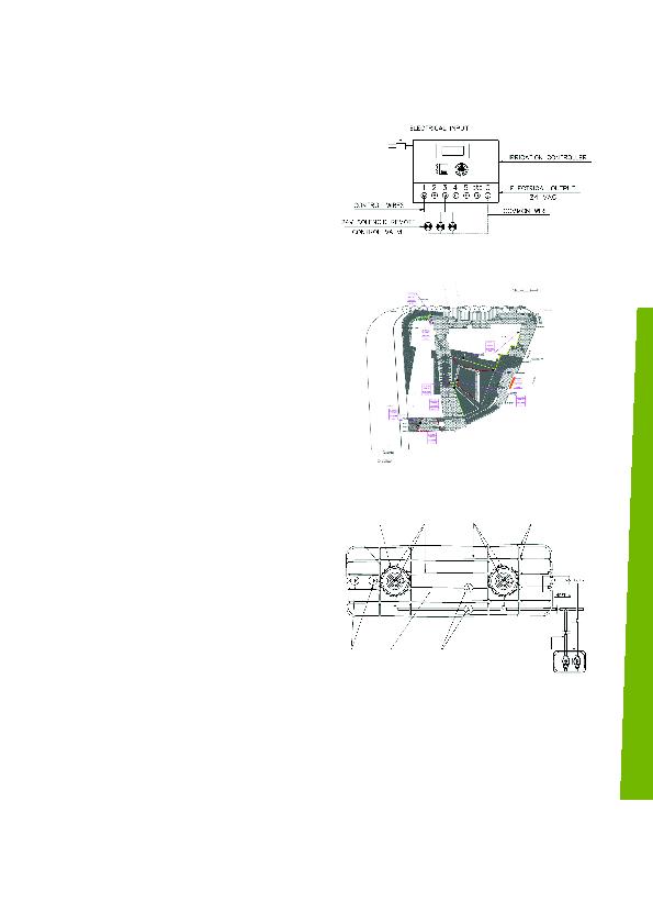
equipped it with a controller that connected command valves,
flow and soil moisture sensors. The controller and remote control
devices allow the punctual supply of irrigation water to the
landscaped areas (Figure 5).
based on plant types, waterusage category, and wind and sun
exposure (Figure 6). These zones were controlled by separate
valves delivering the necessary water amount. The valves, all
remotecontrolled, can control one irrigation zone at a time.
What is more, they feature pressureregulating devices that can
lead to water savings of up to 50%.
systems that supply water slowly and directly to the plant root
bulb. Savings from such subsurface dripline systems can reach
up to 40% over conventional water systems. The special drip
systems have exceptional advantages:
looped or in an open grid.
a selfpressure compensating feature that minimizes the water's
outflow fluctuations, resulting in a highuniform water distribution.
cover bed
high point
at low end
for trees and ground
cover beds on
separate zones
elbor or cross
in bed or around tress
LEED calculation forms proved that the design reduced total water use by an average of 59% across the three parcels.
of the LEED Water Efficient Landscaping WE Credit 1 for all three parcels. The experience cemented our engineers' skills in a field that is fast
becoming essential in today's thirsty cities.