d
u
e
t
o
s
w
e
l
li
n
g
(
c
m
)
ds
0.0
1
10
St
r
ain
100
Pressure (kPa)
dewd
Suggested swelling pressure (kPa) vs Strain
1000
0.5
1.0
1.5
2.0
2.5
3.0
3.5 %
%
%
%
%
%
%
%
-400
-600
-200
0
-1000
-1200
0.0
5
-5
10
-10
10
-15
10
-20
10
-25
5
10
15
20
25
Stresses vs. Depth at the tunnel's centerline
Stresses change that
causes swelling
Initial stress (kPa)
Stresses change that
causes swelling
Tunnel
excavation
-800
Final stress (kPa)
Swelling pressure (kPa)
0
200
400
600
800
1000
1200
1400
1600
1800
2000
Max. axial force
[kN/m]
Max. bending moment
[kN.m/m]
Max. shear force
[kN/m]
Without considering swelling
Considering swelling
0
1
2
3
4
5
10-
8-
6-
4-
2-
0
2
4
6
8
10
D
i
s
p
l
a
ce
m
e
n
t
Distance from the centerline of the tunnel axis (m)
Depth (m)
Pressure (kPa)
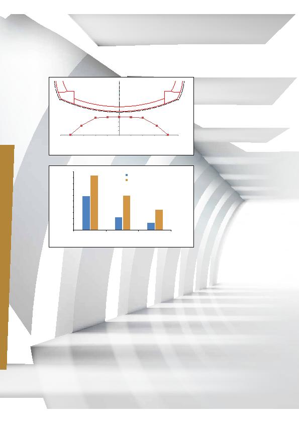
The deformation pattern (Figure 3) we obtained was applied at the bottom of the invert as prescribed
displacement in order to model the swelling pressures on the lining.
Figure 3
Figure 4
Figure 4 shows the impact of swelling on the final lining, by comparing the resulting forces and moments for
two scenarios: with and without considering the swelling pressures.
Temporary support and final lining
The temporary support of the tunnel consisted of a combination of shotcrete, wire mesh, steel arches, and rock
bolts (Figure 5).
The tunnel invert was immediately placed after the last stage of excavation, so it could inhibit the deformations
due to swelling.
The reinforcements were assembled outside the tunnel in order to minimize the time between both activities.
However, the reinforcement cages turned out to be very heavy to carry and move easily. Therefore, it was
necessary to reduce the reinforcement and accelerate the task on site. For this, the curvature of the invert was
increased to force the lining to take the straining actions by axial force and hence decrease the moment and
eventually the reinforcement (Figure 6).
36
i10 |
A cure for swelling