- Page 1
- Page 2
- Page 3
- Page 4
- Page 5
- Page 6
- Page 7
- Page 8
- Page 9
- Page 10
- Page 11
- Page 12
- Page 13
- Page 14
- Page 15
- Page 16
- Page 17
- Page 18
- Page 19
- Page 20
- Page 21
- Page 22
- Page 23
- Page 24
- Page 25
- Page 26
- Page 27
- Page 28
- Page 29
- Page 30
- Page 31
- Page 32
- Page 33
- Page 34
- Page 35
- Page 36
- Page 37
- Page 38
- Page 39
- Page 40
- Page 41
- Page 42
- Page 43
- Page 44
- Page 45
- Page 46
- Page 47
- Page 48
- Page 49
- Page 50
- Page 51
- Page 52
- Page 53
- Page 54
- Page 55
- Page 56
- Page 57
- Page 58
- Page 59
- Page 60
- Page 61
- Page 62
- Page 63
- Page 64
- Flash version
© UniFlip.com
serviceability design of floor structures | i8
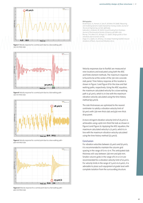
Bibliography: Ebrahimpour, A., Hamam, A., Sack, R., & Patten, W. (1996). Measuring and modeling dynamic loads imposed by moving crowds. Journal of Structural Engineering, 122 (12), 1468-1474. Galbraith, G., & Barton, W. (1970). Ground loading from footsteps. Journal of the Acoustical Society of America, 48, 1288- 1292. Murray, T. M., Allen, D. E., & Ungar, E. E. (1997). Design guide 11: Floor vibrations due to human activity. Ungar, E. E., Zapfe, J. A., & Kemp, J. D. (2004). Predicting footfall-induced vibrations of floors. Sound and Vibration, 16-22. Figure 7 Velocity response for a central point due to a slow walking path 330 mm thick slab
Figure 8 Velocity response for a central point due to a fast walking path 330 mm thick slab
Velocity responses due to footfall are measured at nine locations and evaluated using both the AISC and finite element methods. The maximum response is found to be at the center of the 330 mm concrete slab panel. Time history response at this location is shown in Figure 7 and Figure 8 for the slow and fast walking paths, respectively. Using the AISC equation, the maximum calculated velocity for a slow walking path is 47 μm/s, which is in line with the maximum vibration velocity calculated using the time history method (43 μm/s). The slab thicknesses are optimized to the nearest centimeter to satisfy a vibration velocity limit of 50 μm/s with 330-mm thick slab and 430-mm thick drop panel. A more stringent vibration velocity limit of 25 μm/s is achievable using a 400-mm thick flat slab as shown in Figure 9 and Figure 10. Applying the AISC equation, the maximum calculated velocity is 21 μm/s, which is in line with the maximum vibration velocity calculated using the time history method (23 μm/s).
Figure 9 Velocity response for a central point due to a slow walking path 400 mm thick slab
Conclusion
For vibration velocities between 25 μm/s and 50 μm/s, it is recommended to maintain the column grid spacing in the range of 6 m x 9 m. The anticipated slab thickness will vary between 330 mm and 400 mm. Smaller column grids in the range of 6 m x 6 m are recommended for a vibration velocity limit of 12 μm/s. For velocity limits in the range of 3 μm/s to 6 μm/s, it is advisable to place such equipment at grade level with complete isolation from the surrounding structure.
Figure 10 Velocity response for a central point due to a fast walking path 400 mm thick slab
43