- Page 1
- Page 2
- Page 3
- Page 4
- Page 5
- Page 6
- Page 7
- Page 8
- Page 9
- Page 10
- Page 11
- Page 12
- Page 13
- Page 14
- Page 15
- Page 16
- Page 17
- Page 18
- Page 19
- Page 20
- Page 21
- Page 22
- Page 23
- Page 24
- Page 25
- Page 26
- Page 27
- Page 28
- Page 29
- Page 30
- Page 31
- Page 32
- Page 33
- Page 34
- Page 35
- Page 36
- Page 37
- Page 38
- Page 39
- Page 40
- Page 41
- Page 42
- Page 43
- Page 44
- Page 45
- Page 46
- Page 47
- Page 48
- Page 49
- Page 50
- Page 51
- Page 52
- Page 53
- Page 54
- Page 55
- Page 56
- Page 57
- Page 58
- Page 59
- Page 60
- Page 61
- Page 62
- Page 63
- Page 64
- Flash version
© UniFlip.com
i8 | serviceability design of floor structures
Figure 3 Partial floor configuration for the Shared Lab Building
Case study
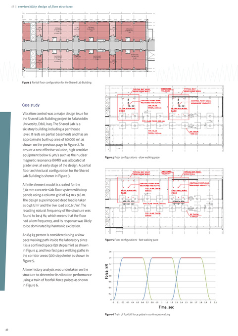
Vibration control was a major design issue for the Shared Lab Building project in Salahaddin University, Erbil, Iraq. The Shared Lab is a six-story building including a penthouse level. It rests on partial basements and has an approximate built-up area of 60,000 m2, as shown on the previous page in Figure 2. To ensure a cost-effective solution, high sensitive equipment below 6 μm/s such as the nuclear magnetic resonance (NMR) was allocated at grade level at early stage of the design. A partial floor architectural configuration for the Shared Lab Building is shown in Figure 3. A finite element model is created for the 330 mm concrete slab floor system with drop panels using a column grid of 6.4 m x 9.6 m. The design superimposed dead load is taken as 0.45 t/m2 and the live load at 0.6 t/m2. The resulting natural frequency of the structure was found to be 4 Hz, which means that the floor had a low frequency, and its response was likely to be dominated by harmonic excitation. An 84-kg person is considered using a slow pace walking path inside the laboratory since it is a confined space (50 steps/min) as shown in Figure 4, and two fast pace walking paths in the corridor areas (100 steps/min) as shown in Figure 5. A time history analysis was undertaken on the structure to determine its vibration performance using a train of footfall force pulses as shown in Figure 6.
Figure 4 Floor configurations - slow walking pace
Figure 5 Floor configurations - fast walking pace
Figure 6 Train of footfall force pulse in continuous walking
42