- Page 1
- Page 2
- Page 3
- Page 4
- Page 5
- Page 6
- Page 7
- Page 8
- Page 9
- Page 10
- Page 11
- Page 12
- Page 13
- Page 14
- Page 15
- Page 16
- Page 17
- Page 18
- Page 19
- Page 20
- Page 21
- Page 22
- Page 23
- Page 24
- Page 25
- Page 26
- Page 27
- Page 28
- Page 29
- Page 30
- Page 31
- Page 32
- Page 33
- Page 34
- Page 35
- Page 36
- Page 37
- Page 38
- Page 39
- Page 40
- Page 41
- Page 42
- Page 43
- Page 44
- Page 45
- Page 46
- Page 47
- Page 48
- Page 49
- Page 50
- Page 51
- Page 52
- Page 53
- Page 54
- Page 55
- Page 56
- Page 57
- Page 58
- Page 59
- Page 60
- Page 61
- Page 62
- Page 63
- Page 64
- Flash version
© UniFlip.com
i8 | serviceability design of floor structures
Serviceability design of floor structures under footfall-induced vibrations
By Dr. Muhannad Fakhouri, Seif Al-Jundi and Marwan Kobrosly, Dar Al-Handasah
Strength design and deflection serviceability limit were once a structural engineer's main concern. In recent years, however, the trend of building large spans and lighter structures has dramatically increased the need for structure assessments for vibration control.
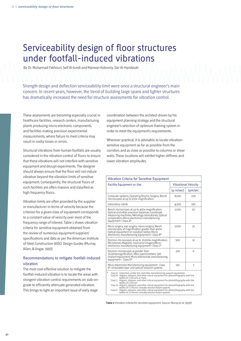
These assessments are becoming especially crucial in healthcare facilities, research centers, manufacturing plants producing micro-electronic components, and facilities making precision experimental measurements, where failure to meet criteria may result in costly losses or errors. Structural vibrations from human footfalls are usually considered in the vibration control of floors to ensure that these vibrations will not interfere with sensitive equipment and disrupt experiments. The designer should always ensure that the floor will not induce vibration beyond the vibration limits of sensitive equipment. Consequently, the structural floors of such facilities are often massive and classified as high frequency floors. Vibration limits are often provided by the supplier or manufacturer in terms of velocity because the criterion for a given class of equipment corresponds to a constant value of velocity over most of the frequency range of interest. Table 1 shows vibration criteria for sensitive equipment obtained from the review of numerous equipment suppliers’ specifications and data as per the American Institute of Steel Construction (AISC) Design Guides (Murray, Allen, & Ungar, 1997).
coordination between the architect driven by his equipment planning strategy and the structural engineer’s selection of optimum framing system in order to meet the equipment’s requirements. Wherever practical, it is advisable to locate vibrationsensitive equipment as far as possible from the corridors and as close as possible to columns or shear walls. These locations will exhibit higher stiffness and lower vibration amplitudes.
Vibration Criteria for Sensitive Equipment
Facility Equipment or Use
Computer systems; Operating Rooms; Surgery; Bench microscopes at up to 100x magnification; Laboratory robots Bench microscopes at up to 400x magnification; Optical and other precision balances; Coordinate measuring machines; Metrology laboratories; Optical comparators; Micro-electronics manufacturing equipment—Class A* Micro surgery, eye surgery, neuro surgery; Bench microscopes at magnification greater than 400x; Optical equipment on isolation tables; Microelectronics manufacturing equipment—Class B* Electron microscopes at up to 30,000x magnification; Microtomes; Magnetic resonance imagers;Microelectronics manufacturing equipment—Class C* Electron microscopes at greater than 30,000xmagnification; Mass spectrometers; Cell implant equipment; Micro-electronids manufacturing equipment— Class D* Micro-electronics Manufacturing equipment—Class E*; Unisolated laser and optical research systems
*
Vibrational Velocity (μ in/sec)
8,000 4,000 2,000
(μm/sec
200 100 50
1,000
25
500
12
250
6
Recommendations to mitigate footfall-induced vibration
The most cost-effective solution to mitigate the footfall-induced vibration is to locate the areas with stringent vibration control requirements on slab-ongrade to efficiently attenuate generated vibration. This brings to light an important issue of early stage
130
3
Class A: Inspection, probe test, and other manufacturing support equipment. Class B: Aligners, steppers, and other critical equipment for photolithography with line widths of 3 microns or more. Class C: Aligners, steppers, and other critical equipment for photolithography with line widths of 1 micron. Class D: Aligners, steppers, and other critical equipment for photolithography with line widths of ½ micron; includes electron-beam systems. Class E: Aligners, steppers, and other critical equipment for photolithography with line widths of ¼ micron; includes electron-beam systems.
Table 1 Vibration criteria for sensitive equipment. Source: Murray et al. (1997)
40