Only one tower was designed with a piled foundation (purple
area in figure 3). This was done to allow a safe transmittal of the
structural loads to the lower deep sound bedrock, for which the
replacement solution was judged to be uneconomical.
method to a discrete one
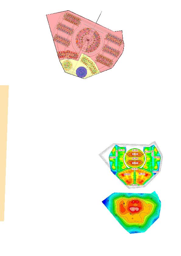
uniform modulus of subgrade reaction k under each tower
(as shown in Figure 4). The mat area was divided into large zones,
for which a specific average k value was considered.
in Figure 5) appeared rough. Importantly, no significant
variability was identified between successive structural
columns/core elements.
strategy. The discrete area method was applied to the
60,000 m
the project's large mat foundation (see Figure 6).
the founding rock, the anticipated structural loads and the
distribution of those loads across the foundation. As expected,
softer and more representative k values emerged for elements
in the center of the mat. They increased towards the mat edges,
with maximum values typically appearing at the mat corners.
foundation. The revised analysis clearly shows a gradually varying
settlement that increases with the intensity of the load in the
center and lessens at the extremities, as it should be in reality.
several good practices:
by a 3D simulation of the site constraint, together, led to
selecting the appropriate foundation solution for each tower.
and collaborated on the discrete area method for the design of
the mat foundations.
and the structure's foundations will provide an actual ground
response, and will allow the structural and geotechnical
engineers to validate and calibrate their numerical models, and
consolidate their know-how in the area of study.