
Date28.02.16
AuthorMohammad Mardini
CompanyDar Al-Handasah
LocationKingdom of Saudi Arabia Middle East
Improving the Dammam Correctional Facility’s Soil
Dammam Correctional Facility
The Dammam Correctional Facility is one of four planned facilities commissioned by the Saudi Arabian Ministry of Interior, along with Riyadh, Jeddah and Taif. The planned facility is around 35 km from Dammam and will eventually accommodate 7,300 prisoners.
Dammam’s subsurface conditions
With a sprawling area of 1,545,000 m2 and no less than 190,000 m2 in built‑up area at stake, the project’s soil conditions had to be stable and were therefore a vital primary consideration.
Dar Al‑Handasah’s team began by performing standard penetration tests on drilled boreholes in the ground to evaluate the relative density of the foundation soil. Initial tests revealed that the site was underlain by very loose, loose to medium dense, and dense poorly graded sand with silt. The soil’s relative density increased with depth.
Next, a hydeogeological study was performed. It found that the site was bisected by a major wadi. Moreover, the site was lower than the surrounding area, with external roads raised and acting as a dyke around the site. Groundwater was found at 0.5 m to 1.50 m below ground level.
Finally, chemical analyses of the soil were carried out, and they revealed a calcium carbonate content of about 34% .
The team concluded that Dammam’s soil suffered from several problems that needed their attention:
- Loose sand layers of an average depth of 4 m
- Irregularly distributed soil relative density
- High groundwater levels
- Liquefaction hazards.
Soil improvement: a necessity
How important is soil improvement to building? Very, it turns out. Soil improvement can increase bearing capacity and stability, reduce post‑construction settlements and mitigate the risk of liquefaction. Furthermore, soil improvement has inherent advantages. It eliminates the need for deep foundations and satisfies safe and stable subsurface conditions for buildings at a relatively reasonable cost.
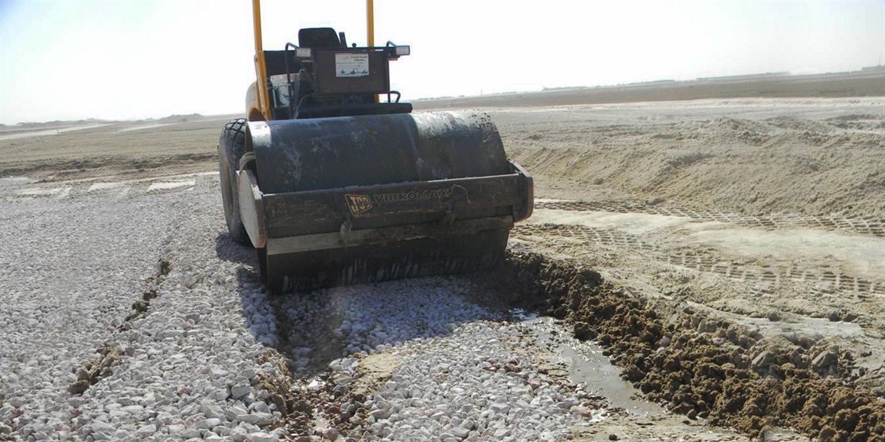
Crushed stone technique
The first process the contractor experimented with was the crushed stones technique. It involves spreading crushed stones on areas with loose granular soil and then compacting these stones with a heavy roller.
Testing the technique
A trial area was set‑up on‑site to study the efficiency of this approach. Layers of crushed stones between 25 mm and 125 mm in size were spread no thicker than 250 mm. The layers were then heavily compacted with vibratory 25‑ton rollers until no further settlement was possible.
Two different tests were conducted on the trial area after it was subjected to the improvement: Standard Penetration Test (SPT) and Cone Penetration Test (CPT). The tests analyzed:
- Liquefaction
- Bearing capacity for the most critical footings
- Settlement analysis for the critical footings considering the interaction effect of adjacent foundations. All calculations were in accordance with the international BS/ASTM standards.
Evaluating the technique
The crushed stone technique proved unsatisfactory: tests showed it to be unsuitable for the prevailing subsurface conditions. This technique was only able to treat layers up to maximum 2 m in depth.
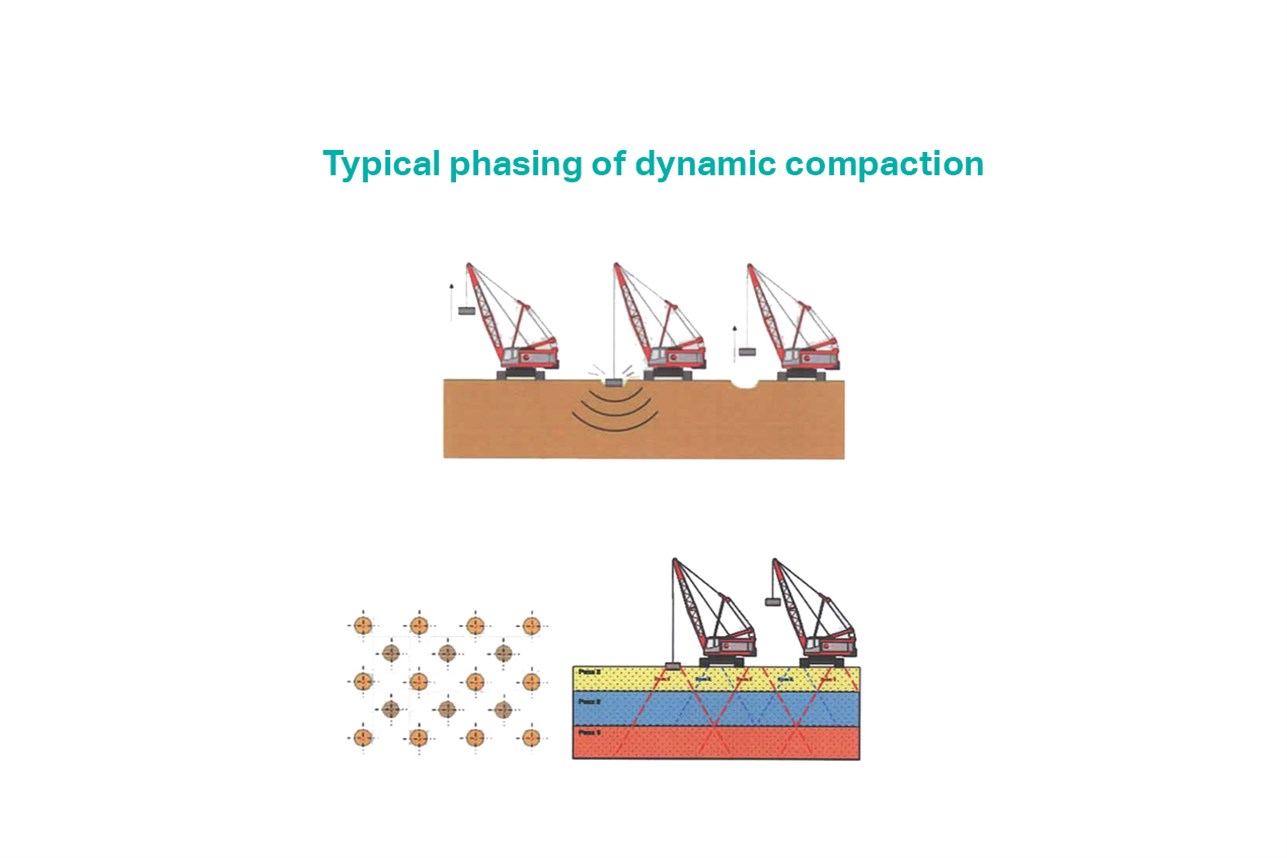
Dynamic Compaction
Finding the first technique inadequate, Dar’s team turned to a second solution, Dynamic Compaction. It targets unsaturated and saturated granular materials, dramatically increases the geotechnical properties of soil, and has the advantage of reaching great depths.
Dynamic Compaction is typically applied to soils with 30‑35% fines content. It is well adapted to large areas and results in uniform ground conditions all over the site.
Cranes lift 35‑ton pounders to a 35‑m height and then release the pounders, delivering, in a single blow, the energy equivalent of 1,200 ton/m. The massive impact of the falling weight triggers a series of actions:
- Immediate densification of granular soils
- Generation of a compression wave that builds pore water pressure causing total or partial liquefaction
- Generation of high energy shear and surface waves that result in a denser soil through the re‑arrangement of the grains
- Speeding up of the consolidation process.
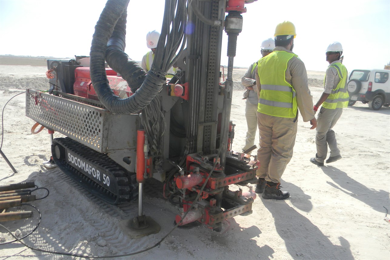
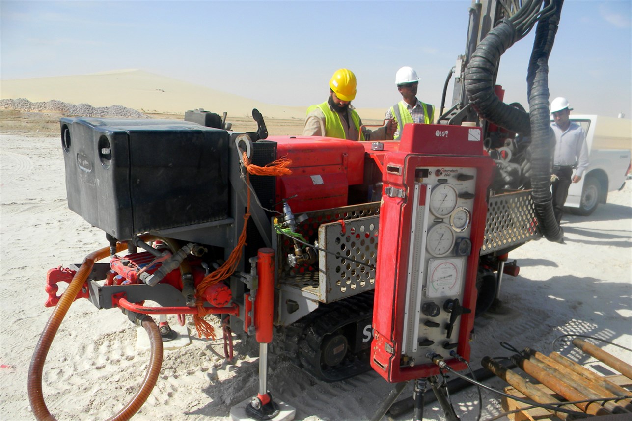
Testing the technique
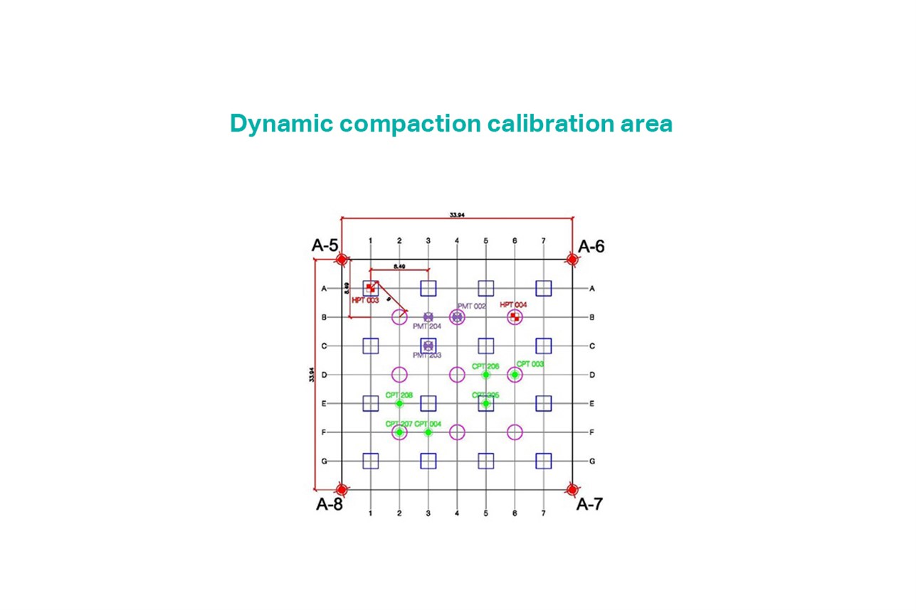
To determine the ideal parameters for the technique, the contractor created an on‑site calibration area. The quality control tools selected were the Pre‑Treatment and Post‑Treatment Cone Penetration Tests (CPT) and the Pressuremeter Tests (PMT).
The tests evaluate subsurface conditions from the relative density point of view, before and after the improvement process. Also, two Heave and Penetration tests were carried out to determine the ideal number of blows.
The assessment parameters were:
- Number of blows per print
- Drop height
- Type and weight of the pounder
- Number of phases and passes.
Evaluating the technique
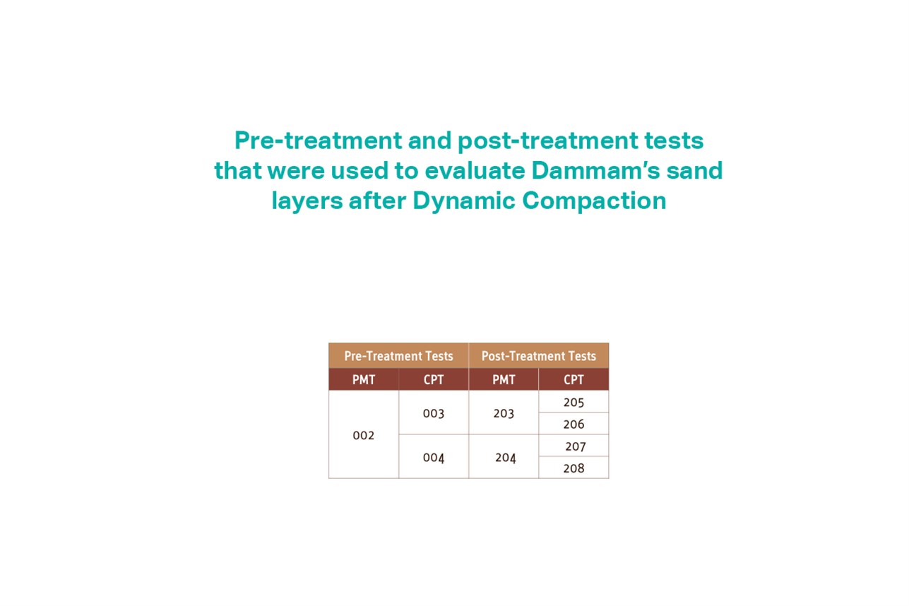
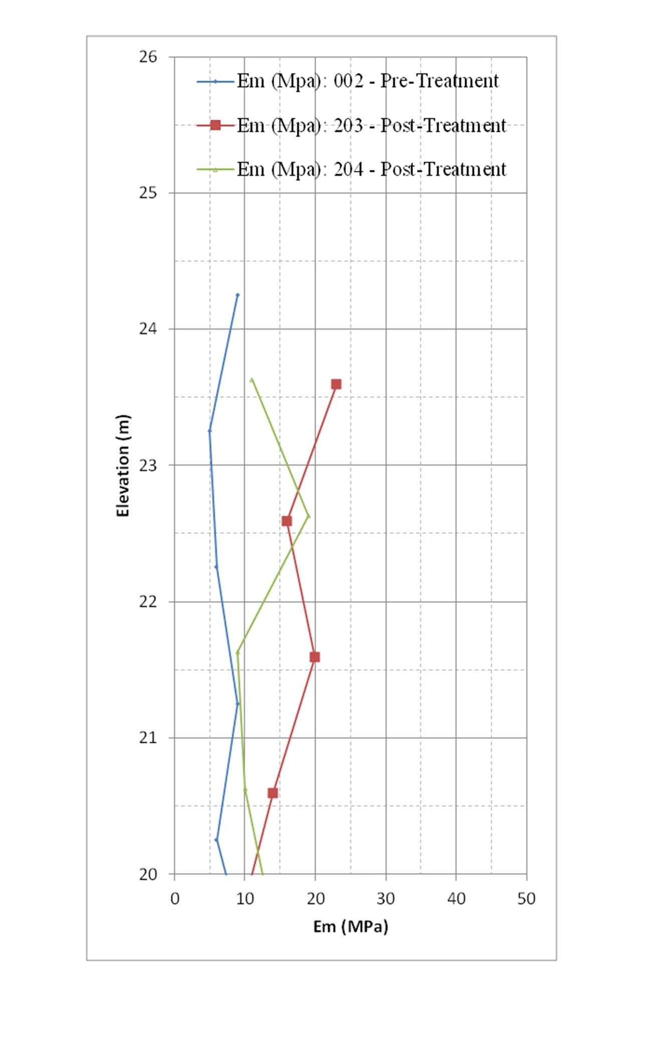
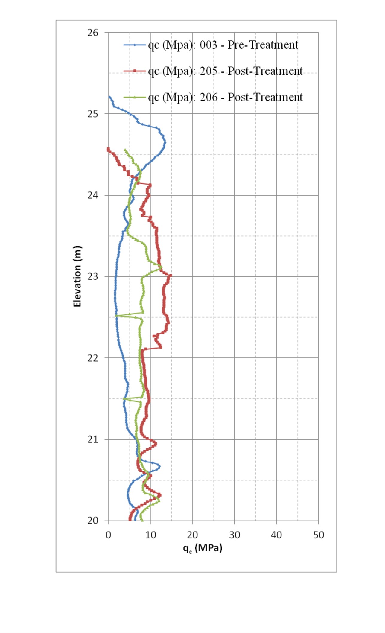
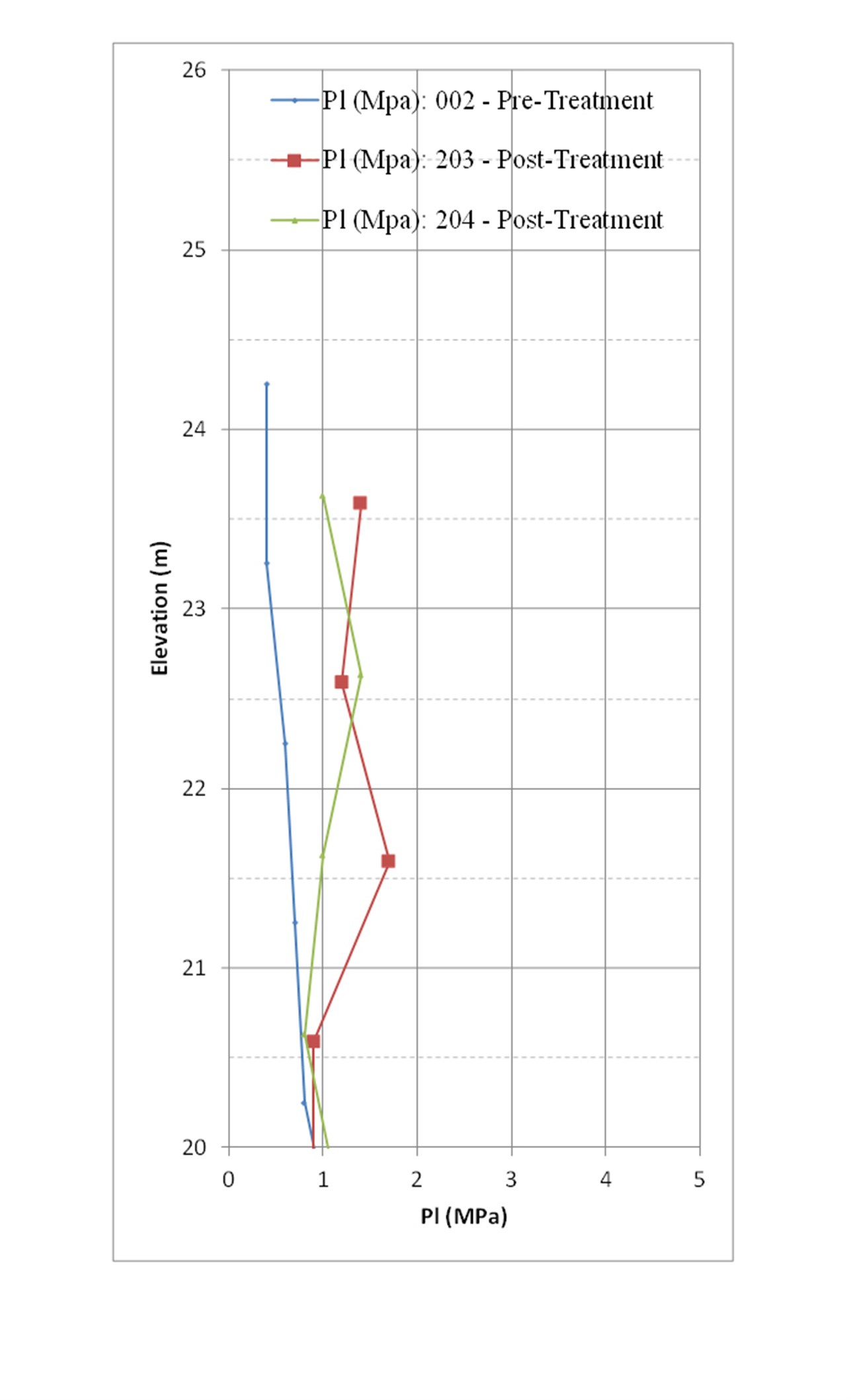
Quality Control Tests’ Results of the Calibration Area Pressuremeter Tests (PMT) were performed to assess the ground condition of the test section before and after improvement. Test (PMT002) was performed before treatment while tests (PMT203 and PMT204) were performed after treatment.
Cone Penetration Test (CPT)
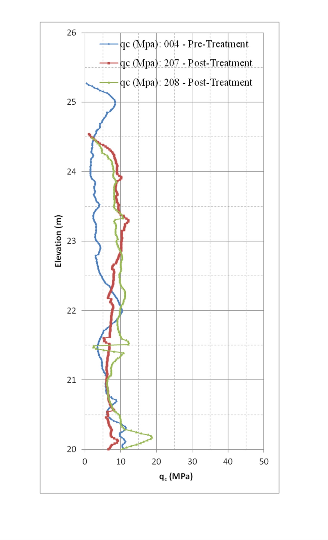
In addition to the PMT, CPTs were also performed to assess the ground condition at the tests locations before and after improvement. CPTs were performed at two zones of the test section. CPT003 (before improvement) and CPT205 and CPT206 (after improvement) were performed at the right hand side (RHS) of the test section, while CPT004 (before improvement) and CPT207 and CPT208 (after improvement) were performed at the left hand side (LHS) of the test section. The reason behind that is to cover a large area of the test section with in‑situ tests to get more confident of the uniformity of the improvement process.
It can be noticed from the CPT and PMT results that the qc, Pl and Em values significantly increased after treatment reflecting the efficiency of the carried out Dynamic Compaction process in enhancing the soil properties and relative density down to an average depth of about 4 m below the ground surface.
Based on calibration areas tests’ results, the following Dynamic Compaction parameters were applied for improving the buildings areas through the project’s site:
- Grid spacing = 6 m x 6 m
- Weight of pounder = 15–18 tons
- Height of drop = 15 m
- 6 blows per print for Phase One
- 4 blows per print for Phase Two.
Relaxed criteria were adopted for roads and future extension areas.
From the calibration area to the entire site:
The results of the calibration area’s Dynamic Compaction were replicated across the entire site. To do this, the team divided the site into segments of 7,500 m2 and applied the following process:
- Leveling and surveying
- Setting the location of the Dynamic Compaction phase in question (there were three phases)
- Executing the phase using the parameters extracted from the calibration area
- Backfilling Dynamic Compaction prints and leveling.
The above process was repeated for all the phases, and then, the final grounds were roller‑compacted.
Learnings
Dar Al‑Handasah’s work on improving the challenging soil of the Dammam Correctional Facility resulted in several important learnings:
- Vibratory rolling is not suitable for deep ground improvement, even when heavy rollers are applied
- Dynamic Compaction successfully improved the loose to very loose semi‑carbonate sandy layers containing high groundwater
- PMT and CPT tests in tandem are essential for quality control and quality assurance to help overcome the shortcomings of using one type of testing
- Parameters of Dynamic Compaction vary with the change in the subsurface conditions
- Using a calibration area on‑site is a key factor in the Dynamic Compaction technique.
Final design criteria
- Bearing capacity: 150 Kpa
- Post‑construction maximum allowable settlement: 25 mm under service loads
- Differential settlement as an angular distortion tolerable limit: 1/500
- Liquefaction factor of safety = 1.3
Images
0 of 0
of